Hybrid System
Use this page to add a boiler and/or cooling tower to the selected Zone Group. An unlimited number of hybrid systems are allowed, although only one may be active at a given time.
Hybrid System Name
- Name Name the hybrid system currently being designed. Since an unlimited number of hybrid systems are allowed, the name should be unique to avoid confusion.
Peak Block Load Reduction
Specify the amount of peak load reduction due to boiler/cooling tower addition to the system.
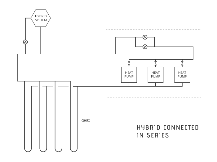
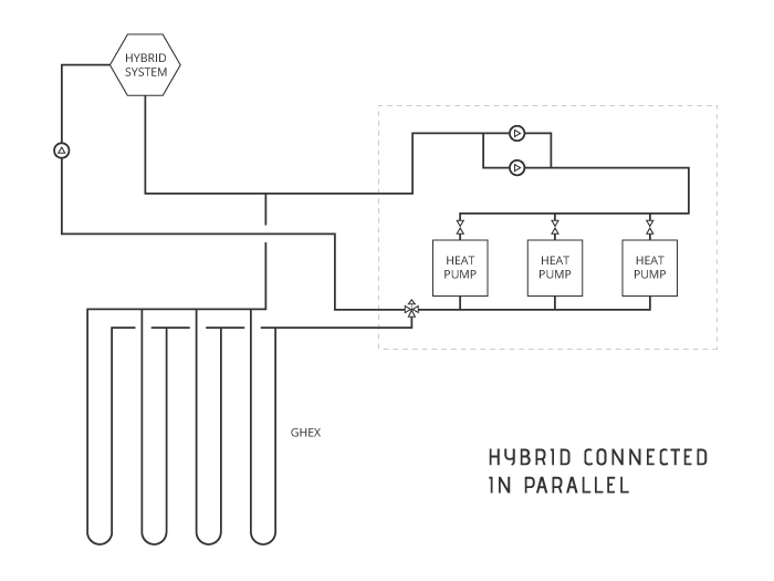
- Connect Cooling Tower/Boiler in Parallel Select this box if the hybrid system is to be connected in parallel with the GHEX.
- This will affect the calculated flow requirements for the GHEX.
- For a series-connected hybrid system, the GHEX must accommodate full system flow, regardless of the peak load reduction and associated flow requirements of the cooling tower/boiler.

- For a parallel-connected hybrid system, the GHEX only needs to accommodate the flow associated with the reduced peak loads when a hybrid system is in use.

-
Percentage of Cooling Peak Block to Cooling Tower/Boiler Specify the percentage of peak load that is to be covered by hybrid system operation.
- For hybrid systems used to "pre-condition" the GHEX (i.e. - run at night or during off-peak time periods) but will not operate during peak load conditions, the percent reduction should be set to zero.
- The resulting zone group loads will be clamped according to the maximum peak load reduction that is specified and may not be reduced by the same amount across all time blocks.
- Consider the following example of a zone group with a 1200 kBtu/hr (100-ton) peak load that is to be reduced by 480 kBtu/hr (40-tons) with a hybrid system (40% covered by hybrid) and has the following load distribution:
-
Time Block Peak Load by Time Block Reduction by Time Block Clamped Loads (with Hybrid) 8:00 am - 12:00 pm 900 kBtu/hr (180 kBtu/hr) 720 kBtu/hr 12:00 pm - 4:00 pm 1200 kBtu/hr (480 kBtu/hr) 720 kBtu/hr 4:00 pm - 8:00 pm 1200 kBtu/hr (480 kBtu/hr) 720 kBtu/hr 8:00 pm - 8:00 am 600 kBtu/hr (0 kBtu/hr) 600 kBtu/hr
-
Peak Block Reduction The maximum amount of peak block reduction by the hybrid system, calculated according to the percentage specified.
- Required Capacity The required capacity of the cooling tower/boiler to reduce the peak loads by the specified amount
- This value will be a function of system efficiency (EER/COP) and associated heat of rejection/extraction.
Ground Energy Offset
- Percentage of Energy Dissipated/Added Specify the percentage of annual ground energy requirements that will be offset by hybrid system operation.
- Cooling Tower/Boiler Energy The amount of ground load that is offset by the hybrid system, calculated according to the percentage specified.
-
Run Hours at Capacity The calculated number of hours that the hybrid system must operate at the specified capacity to offset the specified amount of annual ground energy.
-
Annual Energy Breakdown This graph shows:
- The portion of the cooling energy (heat of rejection) that is covered by the GHEX relative to the energy dissipated through the cooling tower.
- The ground load imbalance, which is the difference between the heat of rejection (cooling) and heat of extraction (heating) after the hybrid energy offset is accounted for
- The portion of the heating energy (heat of extraction) that is covered by the GHEX relative to energy added by the boiler.
Additional Resource
For more information on hybrid system design, refer to pages 34.22-34.24 in Chapter 34 - Geothermal Energy in the ASHRAE HVAC Applications Handbook (2015)
Object Summary
The Object Summary is displayed to the left of the main page.
- Cooling mode calculation results are highlighted in BLUE.
- Heating mode calculations results are highlighted in YELLOW.
- Note that when an input is changed, the calculation results will not display on screen until the page is saved.
- Individual Hybrid System and the aggregate Zone Group outputs are shown on the top-half of the left-hand output panel. The Active GHEX Summary outputs (which are based on the active GHEX in the zone group and are based on all space conditioning, hot water zone, and hybrid load information) are shown on the bottom-half of the output panel.
Peak Block Clamping
Hybrid Peak Reduction
- View the clamped load reductions (by time block) for the current Hybrid System according to the information entered. Keep in mind that the loads will be clamped according to the maximum peak load reduction that is specified and may not be reduced by the same amount across all time blocks.
- HEATING LOAD REDUCTION BY TIME BLOCK The calculated heating load decrease (by time block) due to specified percentage for the current Hybrid system.
- COOLING LOAD REDUCTION BY TIME BLOCK The calculated cooling load decrease (by time block) due to specified percentage for the current Hybrid system.
Zone Group Design Day
View the aggregate loads for the active Zone Group.
- HEATING LOAD BY TIME BLOCK The calculated heating loads (by time block) for all active space conditioning, hot water and hybrid systems in the Zone Group.
- COOLING LOAD BY TIME BLOCK The calculated cooling loads (by time block) for all active space conditioning, hot water and hybrid systems in the Zone Group.
- Full Load Run Hours The weighted average value for FLRHs, which considers all active space conditioning, hot water and hybrid systems in the Zone Group.
Active GHEX Summary
- Active GHEX The active GHEX for the zone group, for with the calculation results in the Active GHEX Summary are based on.
-
Type The configuration (vertically-bored or horizontally-bored) of the Active GHEX for the zone group.
-
Design Flow The total flow that the GHEX must accommodate. This value will affect the calculations for LWT, loop flow, loop velocity, Reynold's number and head loss.
- Design flow is calculated based on the installed equipment capacity or peak block load and/or peak hot water generation demand for the system (depending on the Flow Analysis Mode specified for the Zone Group).
- Design flow is affected by the connection method of the hybrid system (series or parallel).
- For a series-connected hybrid system, the GHEX must accommodate full system flow, regardless of the peak load reduction and associated flow requirements of the boiler/cooling tower.
- For a parallel-connected hybrid system, the GHEX only needs to accommodate the flow associated with the reduced peak loads when a hybrid system is in use.
- Y1 Temp. Penalty The temperature change of the soil after the first year of system operation.
- This change results from imbalances between the amount of heat added to the ground in cooling and removed from the ground in heating and will reduce GHEX effectiveness over the long-term if unaccounted for.
- The calculated temperature change accounts for thermal interference from adjacent bores, which is a function of the annual NET GROUND ENERGY load as well as loopfield geometry (grid/layout and bore spacing). The designer is faced with selecting a layout and separation distance that is reasonable in order to minimize required land area without causing large increases in required bore length (due to temperature penalty).
- A negative value indicates that the annual ground load imbalance is HEATING dominant.
- A positive value indicates that the annual ground load imbalance is COOLING dominant.
-
YN Temp. Penalty The temperature change of the soil after N-years of system operation.
- This change results from imbalances between the amount of heat added to the ground in cooling and removed from the ground in heating and will reduce GHEX effectiveness over the long-term if unaccounted for.
- The calculated temperature change accounts for thermal interference from adjacent bores, which is a function of the annual NET GROUND ENERGY load as well as loopfield geometry (grid/layout and bore spacing).
- The designer is faced with selecting a layout and separation distance that is reasonable in order to minimize required land area without causing large increases in required bore length (due to temperature penalty).
- A negative value indicates that the annual ground load imbalance is HEATING dominant.
- A positive value indicates that the annual ground load imbalance is COOLING dominant.
WARNING
Use of excessive values in the Year-N field will result in extremely conservative estimates for the Year-N temperature penalty, thus increasing overall design lengths and system first cost. Keep in mind that this calculation assumes (1) the building load and annual equivalent FLRHs for the Zone Group are accurate without large margin of error and/or safety factor and (2) the building will be used in exactly the same manner every year for N-Years.
Y1 Length/Bore The depth of each bore required to ensure the system will operate within designer-specified limits during the first year of system operation.
- This parameter does not account for the long-term effects of ground load imbalances. Outside of the inputs provided on the GHEX design page,
- Y1 Length/Bore is most sensitive to the peak loads and the minimum/maximum EWTs specified for the Zone Group.
- Y1 Length/Bore will also be a function of the number of bores in the selected layout, calculated to be (Y1 Total Length) / (Number of Bores).
- This parameter accounts for the long-term effects of ground load imbalances. Outside of the inputs provided on the GHEX design page,
- YN Length/Bore is most sensitive to the peak loads, the minimum/maximum EWTs specified for the Zone Group and annual equivalent FLRHs.
- YN Length/Bore will also be a function of the number of bores in the selected layout, calculated to be (YN Total Length) / (Number of Bores).
- This is the individual bore depth to specify in the project design documents to ensure that the system will operate within designer-specified limits in both the short- and long-term.
Energy Requirements
- Space Conditioning The calculated amount of energy rejected to the ground in cooling mode and extracted from the ground in heating mode, which is a function of the peak loads, annual equivalent FLRHs and equipment efficiencies (EER/COP).
- Hot Water Generation The calculated amount of energy extracted from the ground due to hot water generation, which is a function of the peak hot water demand, annual hot water consumption and equipment heating efficiency (COP).
- Hot water generation will add to the annual heating ground load, as indicated by the value only being shown in the HEATING column.
- Total The total cooling ground load due to space conditioning loads and the total heating ground load due to space conditioning load as well as hot water generation loads.
Energy Sources & Sinks
- Hybrid System The portion of heat of extraction/rejection to/from the building that is covered by active hybrid system for the zone group.
- Ground Energy The portion of heat of extraction/rejection to/from the building that is covered by active GHEX for the zone group.
- Net Ground Energy The difference between the cooling ground load and the heating ground load after accounting for the portion that is covered by the hybrid system.
- A negative value indicates that the annual ground load imbalance is HEATING dominant.
- A positive value indicates that the annual ground load imbalance is COOLING dominant.